Most people never consider the components of a pump until one breaks. If you are not getting water or your basement is flooded, you might know that something is wrong with the pump – but you have no idea what you’re looking at. In this blog, we will break down the parts of a submersible sewage pump to give you a better understanding of how a pump is constructed how the parts fit together to move fluid.
Why should you be able to identify pump repair parts? As with any other piece of mechanical equipment, familiarity with the components can help you understand proper functioning, assist you in diagnosing potential problems and enable you to repair the pump yourself, should you be so inclined.
Plus, a little extra knowledge never hurt anybody.
Pump Components
A pump is composed of two main parts: the volute and the motor. A volute is the curved casing that receives the fluid. The fluid’s rate of flow decreases while the flow pressure increases.
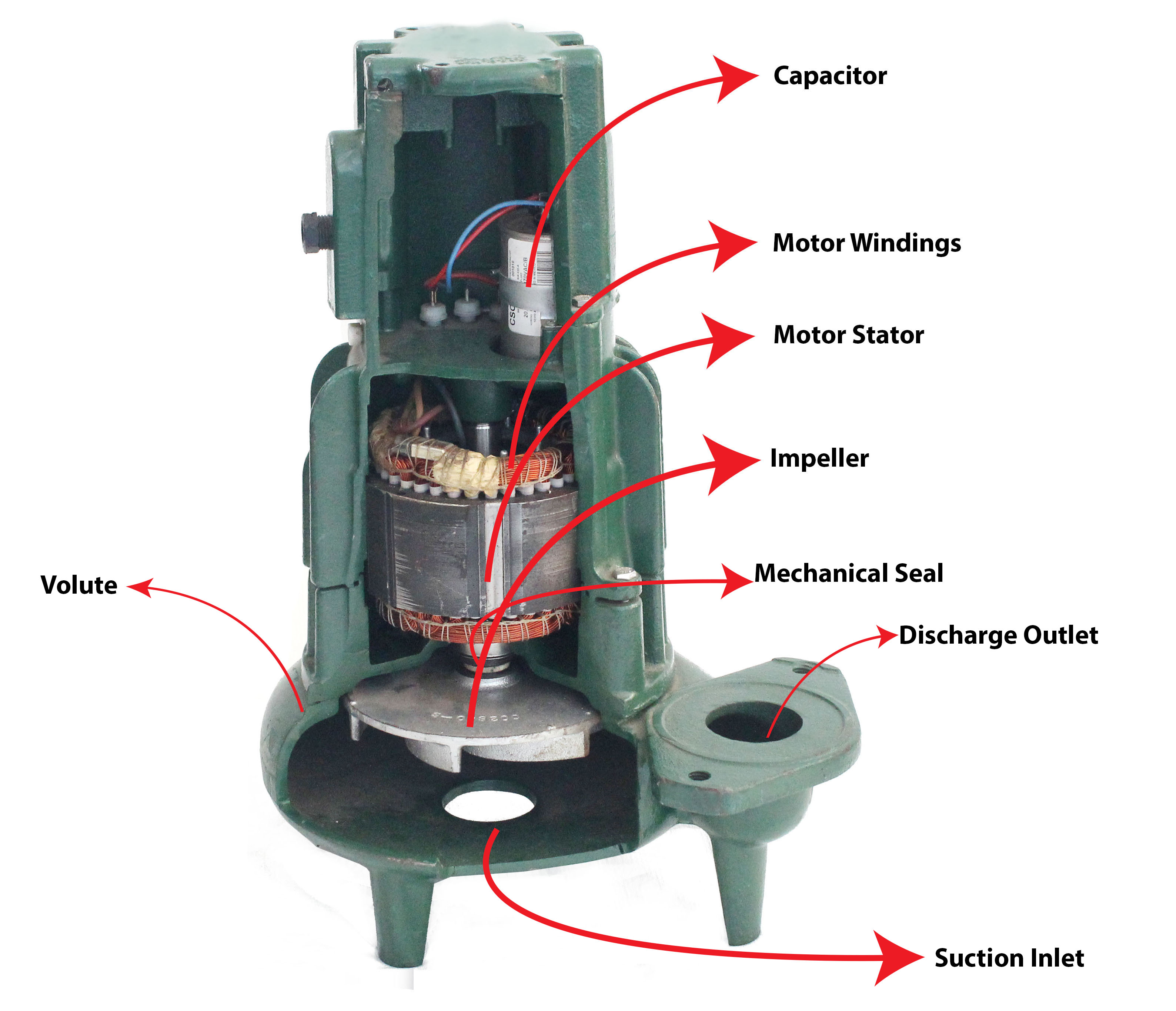
Volute
Inside the volute and connected to the motor shaft is the impeller. An impeller is a rotor used to increase both the pressure and flow of a fluid. There are four components to an impeller:
–The eye, where the fluid enters.
–The veins, which push the fluid.
–The channels, which are the spaces in between the veins where the fluid flows.
–The bore, in which the motor shaft attaches.
Impellers exist in a wide variety of types. All impellers are either single or double suction; single suction impellers allow the fluid to enter through one direction, while double suction types allow fluid to enter on either side of the impeller simultaneously.
Impellers have three main configurations: open, semi-open or closed. Open impellers have a series of vanes attached to the central unit. Semi-open impellers contain the vanes in a wear ring design to allow solids to pass through. Closed impellers have a wear ring completely surrounding the vanes. The wear ring is designed to protect the impeller from degradation over time.
It is important to keep in mind that changing the impeller type and dimensions will change the application, flow and differential head.
The next component is the diffuser. The diffuser increases the flow rate while decreasing flow velocity, which in turn increases flow pressure. Diffusers can come in a ring form separate from the impeller or as vanes on the impeller itself.
Some pumps, like submersible well pumps for instance, will be multi-stage, in which there are multiple levels of the pump, each housing its own impeller and diffuser.
The volute will also feature a suction inlet where the water enters and a discharge outlet from which the water exits.
It is important to understand how the components work together to move fluid. The shaft, powered by the motor, connects to and spins the impeller, creating suction. The suction power brings water into the volute through the inlet and ejects water out through the discharge outlet.
Motor
The next main pump component is the motor or the drive that converts electrical energy into mechanical energy. The motor is the workhorse of the pump, the thing that drives the fluid and allows it to work. The motor can either be fan cooled (TEFC) or oil cooled (ODP).

The motor consists of several parts:
–A rotor: The moving part that turns the shaft.
–A stator: The stationary part of the motor’s electromagnetic circuit.
–The windings, which are wires that are laid in coils, usually wrapped around a laminated soft iron magnetic core so as to form magnetic poles when energized with current.
–The commutator, which consists of slip ring segments used to switch the input of most DC machines and certain AC machines.
–Attached to the rotor is the spline shaft, which attaches at the other end to the impeller. This shaft delivers the mechanical power, transferred from the motor to the volute.
–Covering the motor shaft is the shaft sleeve or bearing. The shaft sleeve supports the applied load while allowing the motion of the shaft and reducing friction.
The power source supplies the electricity which is transferred to the motor by the power cable. The stator consists of the windings and laminations (or thin metal sheets) and form the electromagnetic poles. The commutator alternates these poles which interacts with the rotor, making it turn. The shaft connects to the rotor on one end turning the impeller attached to the other end.
One of the most important components is the mechanical seal, which reduces leakage between the rotating shaft and the stationary pump casing. Two seal faces or surfaces maintain contact at a sealing interface. One seal face rotates with the shaft and one is stationary.

The seal must contain four functional components:
–First, the primary seal face, often constructed with silicon carbide, ceramic or tungsten carbide, is embedded in the pump casing and in the rotating assembly. The seal face rotates with the shaft.
–The secondary seal face is stationary.
–You also need a means of actuation such as a spring, in conjunction with the water pressure itself.
–Finally, a means of drive. In this case, the motor.
The seal sits inside of the seal cover plate. The stationary surface presses against the cover plate and has the other surface rotating with the shaft seal, which slides inside of the entire seal. The configuration creates a watertight barrier that prevents water from leaking through to the motor.
Now you have a basic understanding of the components of your pump and how they fit together to transport whatever fluid you need to transport. Here’s a video of our expert Matt explaining the components.
Write a Comment
Connect With Us
Secure Shopping
Our Memberships
Service Excellence
CALL US: 1-800-429-0800

COMPANY INFORMATION
CUSTOMER SERVICE
BUYERS GUIDES
PRODUCT SUPPORT
Call Toll Free: 1-800-429-0800
 "Ask Inspector PumpHead"

[…] can come in a variety of styles. For instance, this Barnes model is constructed similarly to a sewage pump: the suction inlet is on the bottom of the volute. Water moves by way of impeller through the […]